Time-domain detector readout has moved from bench demonstrations to flight, and it now operates aboard compact ion mass spectrometers on orbit. That shift matters most in ion mass spectrometry, where CubeSats and distributed missions push payloads toward tighter size, weight, and power (SWaP) budgets while still demanding high performance.
This article takes as reference the Compact Ion Mass Spectrometer (CIMS) research presented by Los Alamos National Laboratory during the 36th Annual Small Satellite Conference in 2022. The paper, "An Ultra-Low Resource Ion Mass Spectrometer for CubeSat Platforms" by Carlos A. Maldonado et al., describes a compact ion mass spectrometer architecture combining electrostatic filtering, magnetic analysis, and precision timing electronics for ion detection and localization.
The work places a Time-to-Digital Converter (TDC) inside the detector readout chain. It is a concrete case of precision timing electronics carrying the core measurement in a space instrument.
Why compact mass spectrometers matter in space missions
Ion mass spectrometers are used to study ionospheric outflow, plasma composition, and magnetosphere-ionosphere coupling. These measurements help scientists better understand plasma dynamics, solar wind interaction, and the transport of charged particles through space environments.
Traditional instruments capable of measuring ion flux, energy, and mass have historically required relatively large and power-intensive architectures. The CIMS project approaches this differently by focusing specifically on low-energy plasma populations while drastically reducing resource requirements.
The instrument was designed around:
- Low mass
- Low power
- Compact volume
- Simpler manufacturing approaches
- Compatibility with CubeSat-class missions
According to the paper, the estimated flight resources for CIMS are approximately:
- 5 kg
- 4.8 W
- Less than 1000 cm³

The basic architecture of the CIMS instrument
The proposed CIMS instrument combines several subsystems:
- Laminated collimator
- Electrostatic Analyzer (ESA)
- Magnetic sector analyzer
- Microchannel Plate (MCP)
- Cross-Delay Line (XDL) detector
- Timing and acquisition electronics
The instrument follows a double-focusing mass spectrometer architecture derived from the Mattauch-Herzog geometry, allowing simultaneous observation of multiple ion species distributed spatially along the detector plane.
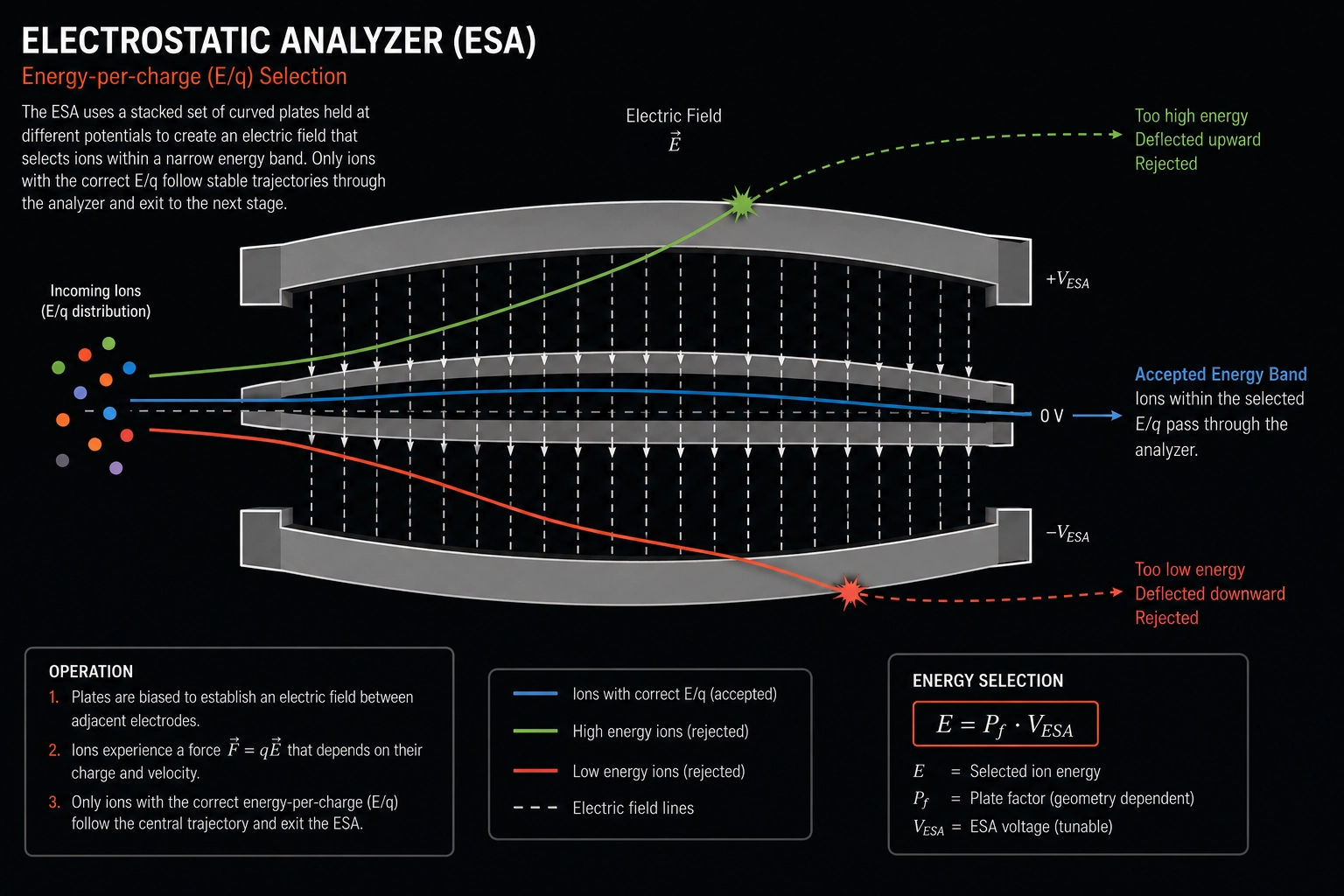
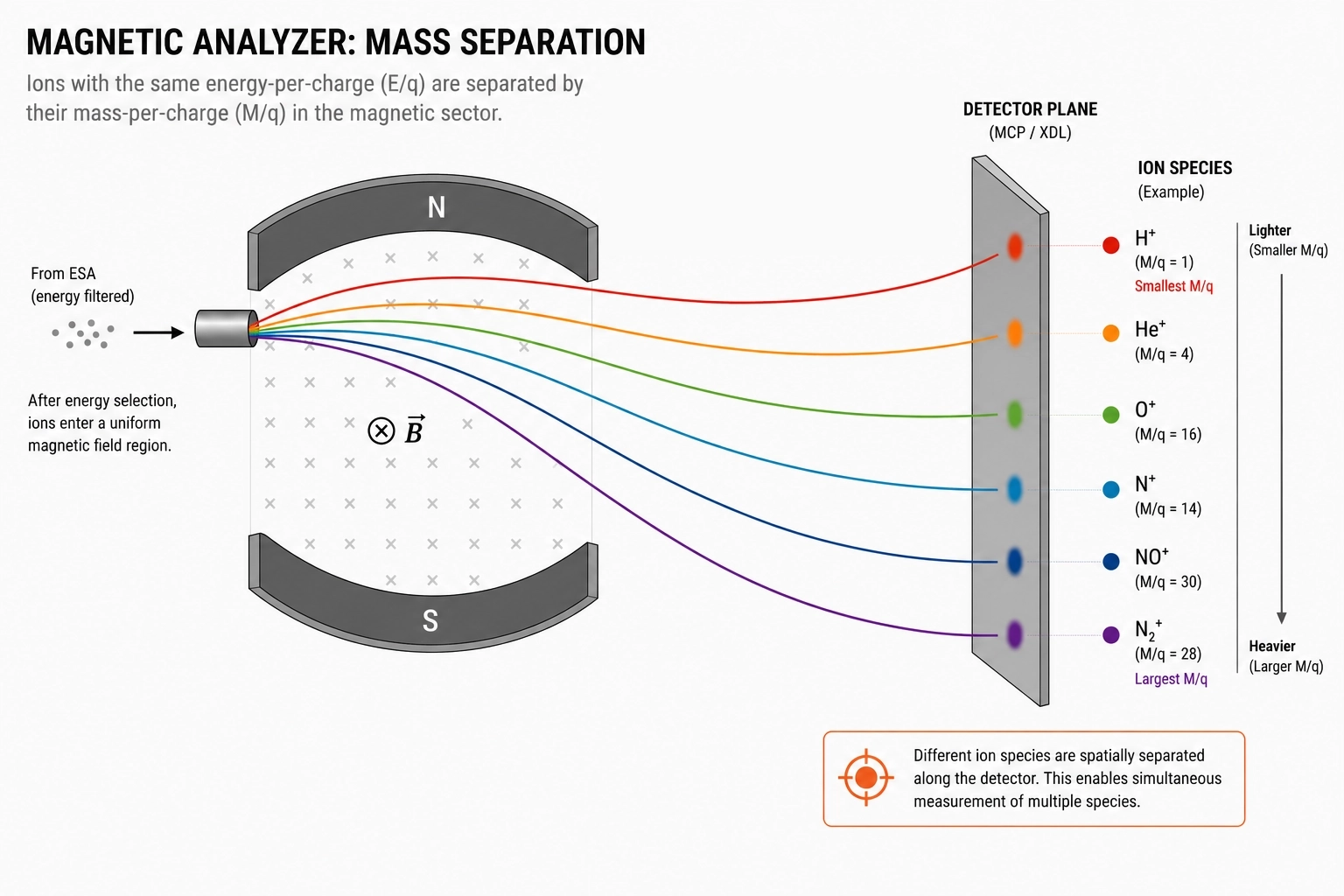
The ESA filters ions according to energy-per-charge (E/q), while the magnetic analyzer separates them by mass-per-charge (M/q).

Electrostatic filtering and ion separation
The front-end ESA is based on a laminated structure using stacked conducting electrode layers with laser-etched apertures and EDM-machined cavities.
The system creates a controlled electric field between plates biased at different voltages. Only ions within a narrow energy band successfully travel through the analyzer.
The accepted ion energy range can be tuned by adjusting the ESA bias voltage, allowing the instrument to target specific plasma populations while maintaining a compact geometry.
Magnetic analysis and mass separation
After energy filtering, ions enter a magnetic sector analyzer based on permanent magnets. The magnetic field separates particles according to momentum-to-charge ratio.
Because the radius of curvature scales with √(m/q) at fixed energy-per-charge, lighter ions curve more sharply (smaller radius) and land closer to the entrance axis, while heavier ions follow a wider arc and land farther out on the detector plane.
This spatial separation allows multiple ion species to be observed simultaneously across the detector plane.
The instrument discriminates ions from light species such as H⁺ and He⁺ through heavier molecular species like NO⁺ and N₂⁺, representative of the ionospheric and thermospheric composition this instrument targets.
From ion detection to detector readout
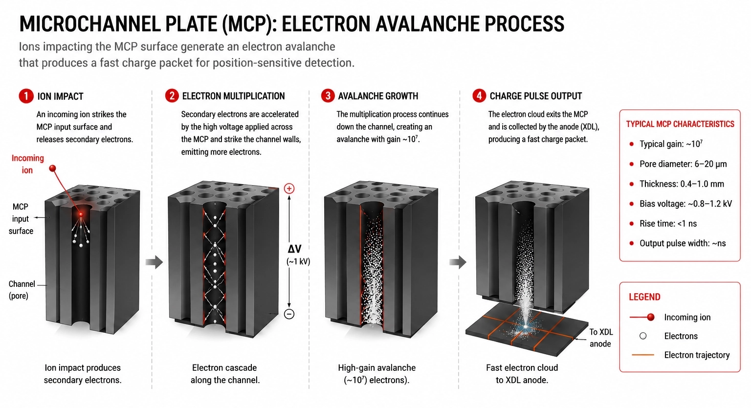
Once ions reach the detector plane, they strike a Microchannel Plate (MCP), generating an electron avalanche with a gain of approximately 10⁷. This electron cloud must then be converted into digital information that accurately represents the location of the ion impact.
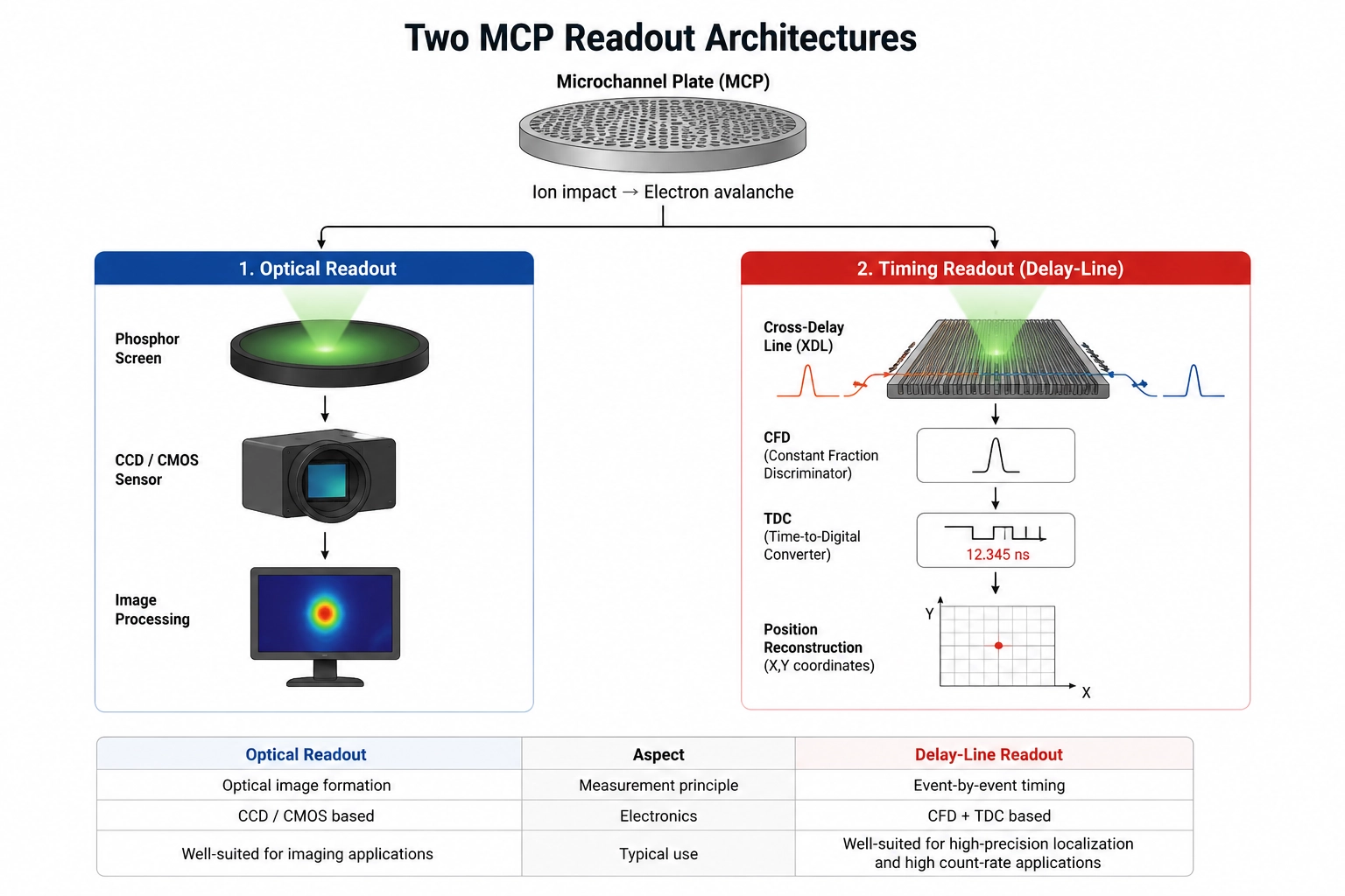
Microchannel Plates can be coupled to different readout architectures depending on the measurement objectives. A common approach uses a phosphor screen followed by a CCD or CMOS image sensor. The electron cloud excites the phosphor screen, producing visible light that is captured as an image. This optical readout method is widely used in imaging applications and offers a straightforward way to visualize detected events.
An alternative approach uses a position-sensitive anode, such as a Cross-Delay Line (XDL) detector. Rather than converting the electron cloud into an optical image, the XDL directly measures the arrival times of electrical signals propagating along orthogonal delay lines. The position of each ion event is then reconstructed from these timing differences.
The CIMS architecture adopts this second approach. By relying on precise timing rather than optical imaging, the instrument achieves accurate event localization while maintaining a compact, low-SWaP architecture well suited for CubeSat and distributed space missions.
Cross-Delay Line readout
The Cross-Delay Line (XDL) detector consists of two orthogonal serpentine delay lines positioned behind the MCP. When the amplified electron cloud reaches the detector, electrical pulses propagate toward both ends of each delay line. Position along each axis is recovered from the difference in arrival time of the pulse at the two ends of the resistive-capacitance delay line.
By measuring these relative arrival times along the X and Y axes, the detector reconstructs the two-dimensional position of every ion impact with high precision. Unlike optical readout approaches, which rely on image formation and subsequent image processing, the XDL architecture determines particle position directly from timing information.
This timing-based approach places stringent requirements on the detector electronics. Any variation in pulse timing directly translates into position uncertainty, making precise and repeatable time measurement fundamental to the overall performance of the instrument. Before these timing measurements can be digitized, however, the detector pulses must first be conditioned to eliminate variations caused by differences in pulse amplitude.
Preparing detector pulses for precise timing measurement
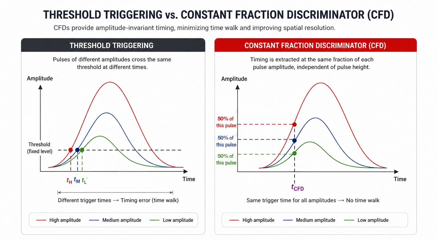
Detector pulses vary in amplitude from event to event. Traditional threshold triggering introduces timing errors because pulses cross thresholds at different moments depending on amplitude.
To mitigate this effect, the CIMS electronics use Constant Fraction Discriminators (CFDs). The CFD provides an amplitude-invariant trigger, so the timing edge handed to the TDC is independent of pulse height.
The CFDs generate stable timing references before signals reach the Time-to-Digital Converter.
Why digitize in the time domain?
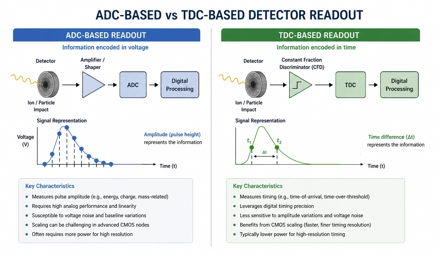
Most detector readout systems rely on Analog-to-Digital Converters (ADCs) to digitize analog signals generated by the detector. In these architectures, the information of interest is represented in the voltage domain, with pulse amplitude corresponding to quantities such as energy, charge, or particle mass.
This approach is widely used and well understood. However, certain detector architectures naturally encode information in the time domain rather than in pulse amplitude. In these cases, a Time-to-Digital Converter (TDC) can provide a more direct path to digitization.
The Cross-Delay Line (XDL) detector used in the CIMS architecture is one such example. Rather than extracting information from pulse height, the detector determines particle position from relative arrival times measured at multiple outputs. The information of interest is therefore inherently encoded as timing differences.
This makes the TDC more than a supporting component. It becomes the primary measurement element within the readout chain, directly converting physical detector events into digital timing information.
MAG-TDC00002 at a glance
The role of the TDC in the detector chain
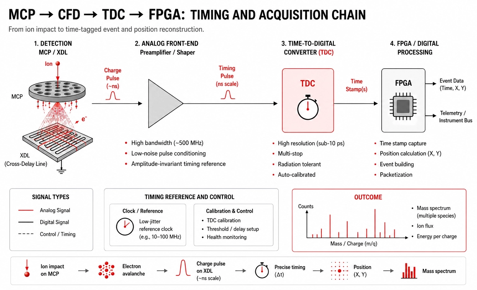
The TDC digitizes the precise arrival times of detector pulses. In the CIMS architecture, these timestamps are used to reconstruct ion positions on the detector plane by measuring timing differences across the Cross-Delay Line detector, which can operate at detection rates above 10⁶ events per second with timing accuracy around 0.1 ns FWHM.
Unlike conventional voltage-domain digitization approaches, the information generated by the XDL detector is inherently encoded as timing. This allows the TDC to act as a direct measurement device rather than as a secondary conversion stage, simplifying the signal chain while preserving measurement precision.
Time interval measurement inside detector systems typically combines coarse timing counters with fine interpolation techniques to achieve picosecond-level resolution. Fine timing interpolation allows the system to resolve events separated by only a few picoseconds. In scientific payloads, this directly impacts:
- Spatial resolution
- Mass discrimination capability
- Event reconstruction accuracy
- Detector throughput
The timing chain inside a CIMS instrument is composed of:
- High-speed amplifiers
- Fast comparators
- CFD circuitry
- TDC integrated circuits
- FPGA-based acquisition electronics
Why modern CMOS technologies favor time-based processing
One reason TDC-based architectures have gained ground is that they benefit directly from semiconductor technology scaling.
As CMOS technologies continue to evolve, transistor switching speeds increase and gate delays become shorter. This naturally enables finer timing resolution in modern TDC architectures. Faster signal transitions also improve timing precision while reducing sensitivity to some voltage-noise sources.
For applications where information is already available in the time domain, this trend allows timing-based signal processing to take advantage of advances in semiconductor technology while maintaining low power consumption and compact implementations. For CubeSat-class payloads in particular, this alignment is decisive: the same scaling that sharpens timing resolution also shrinks the power and area budget a readout consumes, which is exactly the constraint that governs whether an instrument fits a distributed, SWaP-limited platform at all.
Radiation-hardened timing for long-duration missions
Space-based timing electronics must operate under:
- Total Ionizing Dose (TID)
- Single Event Effects (SEE)
- Temperature variation
- Long mission durations
Radiation-induced drift or calibration instability can directly affect scientific measurements.
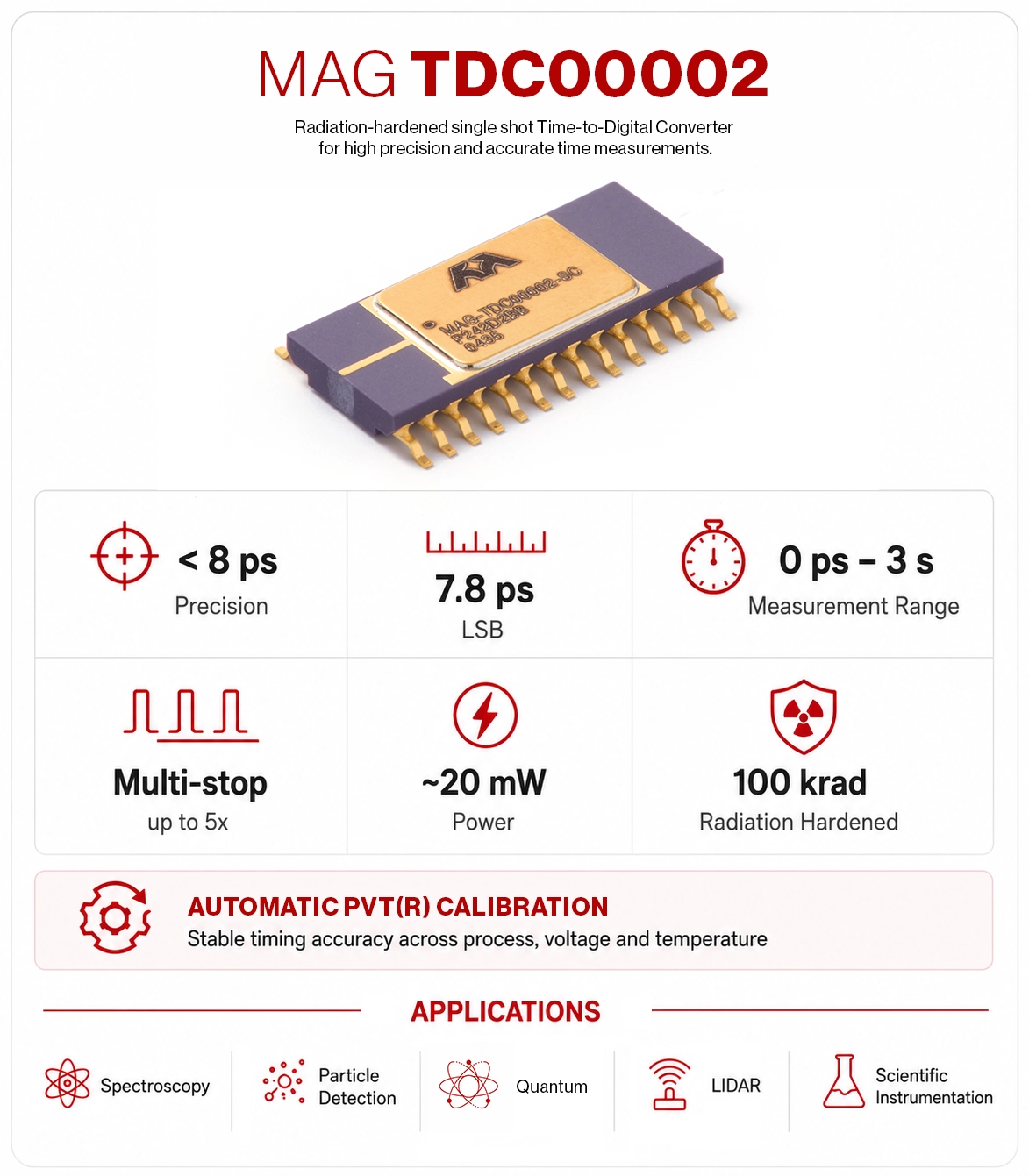
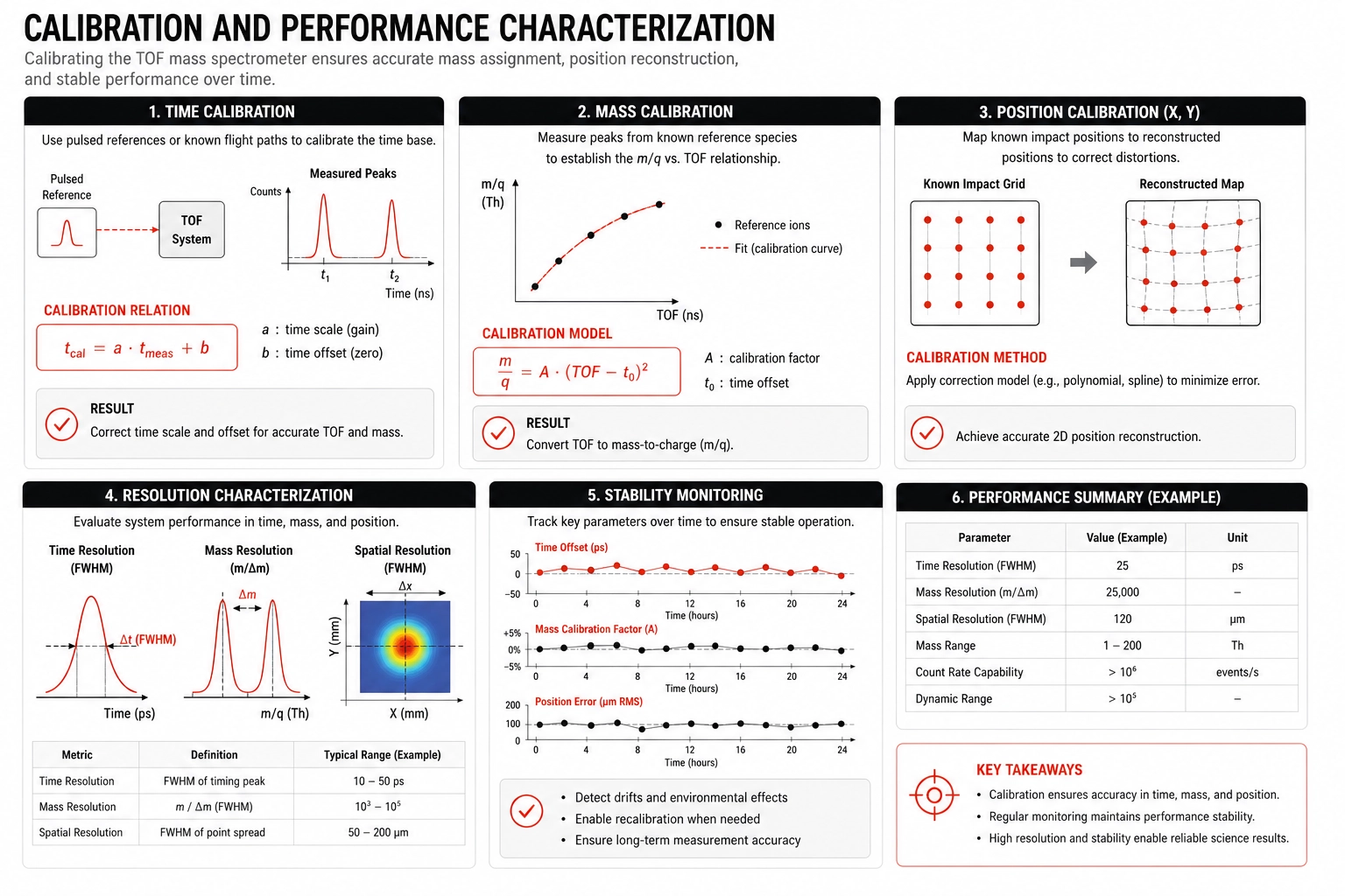
Calibration and characterization are therefore unavoidable in a flight mass spectrometer. Metrics like time-base, mass, and position calibrations all have to be established and maintained on orbit. Every one of those routines, however, rests on an assumption that the underlying time measurement is itself stable. When the timing reference drifts with process, voltage, temperature, or accumulated radiation dose, calibration becomes a moving target: recalibration must run more often, and accuracy degrades between passes. The MAG-TDC00002 addresses this at the source. Its automatic PVT calibration continuously tracks and corrects timing drift, and radiation hardening to 100 krad preserves that stability across a long-duration mission. This means the instrument's calibration and characterization can build on a time base it can trust, rather than one it must constantly chase.
Enabling distributed plasma measurements
One of the major motivations behind compact instruments such as CIMS is enabling distributed measurement architectures.
Constellations of compact sensors could provide simultaneous observations of:
- Ionospheric outflow
- Cold plasma transport
- Magnetospheric mass loading
- Magnetosphere-ionosphere coupling
This requires instrumentation that is:
- Small
- Low-power
- Manufacturable at scale
- Reliable in radiation environments
Precision timing electronics play a central role in enabling these architectures.
By reducing the size, power consumption, and complexity of the instrument, architectures such as CIMS make it practical to deploy multiple sensors across distributed spacecraft platforms.

From synchronization to measurement
Time-domain signal processing is moving out of its old synchronization role and into the primary measurement path, for sensing, localization, and mass discrimination alike. As instruments get smaller, more power-efficient, and more distributed, the information of interest is carried in when an event happens rather than in pulse amplitude; in many detector architectures, timing has become the main source of measurement data.
Compact ion mass spectrometry is one concrete instance of that shift, and it is no longer confined to the bench. Architectures in the CIMS lineage combine compact electrostatic filtering, magnetic analysis, position-sensitive detection, and high-precision timing electronics to reach lower-resource mass spectrometers that suit CubeSats and distributed missions. Time-domain readout of this class is now operating on orbit.
When a detector naturally encodes its information as timing, as a Cross-Delay Line detector does, a Time-to-Digital Converter gives you a direct, efficient, and scalable path to digitization. Together with the gains from modern CMOS, that makes TDC-based architectures a natural choice for instruments working under tight SWaP constraints. Timing resolution sets the quality and usefulness of the science the chain produces, at every stage from single-event localization to constellation-scale sensing.
This is where Time-to-Digital Converters are becoming key building blocks for sensing and instrumentation. The MAG-TDC00002 is one example of how high-resolution, radiation-tolerant timing electronics can enable these architectures, turning detector events into precise, usable scientific data.